Arduino LED Blink tutorial
Table of Contents
Modified: March 6, 2025
Introduction
This tutorial is a brief introduction to the Arduino IDE and is intended to show just how quick it can be to program and deploy software onto your R3aktor development board.
Load the Blink Example
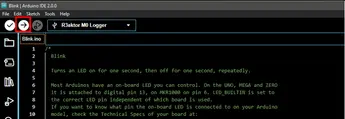
 Begin by opening the Arduino IDE and then select File -> Examples -> 01.Basics -> Blink. A new window will open.
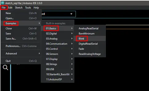
This will load one of the example sketches (what the Arduino IDE uses to refer to programs), which will look something like this:
- // the setup function runs once when you press reset or power the board
- void setup() {
- // initialize digital pin LED_BUILTIN as an output.
- pinMode(LED_BUILTIN, OUTPUT);
- }
- // the loop function runs over and over again forever
- void loop() {
- digitalWrite(LED_BUILTIN, HIGH); // turn the LED on (HIGH is the voltage level)
- delay(1000); // wait for a second
- digitalWrite(LED_BUILTIN, LOW); // turn the LED off by making the voltage LOW
- delay(1000); // wait for a second
- }
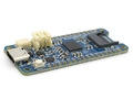
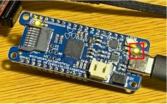
This program (sketch) begins by configuring the digital pin which controls the R3aktor LED as an output. LED_BUILTIN is a special symbol that is used to refer to the built-in R3aktor LED that's located next to the USB-C port.
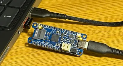
Connect your R3aktor M0 Logger to your computer via USB-C cable.
In the Arduino IDE, make sure you have selected Select Board -> R3aktor M0 Logger.
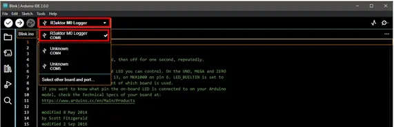
In the top left, select the upload icon (the right facing arrow) to upload the Blink sketch.
After the upload completes, the built-in LED near the USB-C port will begin blinking.
Related Files
No related files.
External Links
No related links.